H-bridge and power
What is a H-bridge?
Microcontrollers are logical devices that function with very modest power. They are not very good at driving loads, like actuators, which typically require power at their inputs. The problem can be solved through an interface capable of injecting power to the actuator as a function of the logical signals of the microcontroller. This is the role of a H-bridge.
A H-bridge is a simple device. It is just a switching circuit connected to a large power generator, as shown in the figure below. The four switches S1-S4 route power to the load, represented in the figure by an encircled M (a motor, in this example).

H bridge. Source: Wikipedia
The switches are typically controlled by the microcontroller.
- If S1 and S4 are closed, and S2 and S3 are open, a positive voltage is applied to the left side of the load (the motor spins in one direction).
- If S2 and S3 are closed, and S1 and S4 are open, a positive voltage is applied to the right side of the load (the motor spins in the other direction).
- If S1 and S3 are closed, and S2 and S4 are open, the same voltage is applied to both sides of the load (the motor does not want to move). The same happens if S2 and S4 are closed, and S1 and S3 are open.
- If either S1 and S2 are closed, or S3 and S4 are closed, the generator is short circuited and terrible things will happen…
So, by using a H-bridge, you can apply a voltage to your load without strong restrictions on the amount of power. Selecting the configuration of the four switches S1-S4 (ON/OFF) you can also decide the direction of the driving voltage to the load. Finally, to modulate the intensity of the voltage, just use PWM, opening and closing S1-S4 at high frequency to generate a suitable average voltage.
MAX14870 Driver
The MAX14870 Driver is a H-bridge that can be used with voltages between 4.5 V to 36 V and can supply up to about 1.7 A continuously, and 2.5 A peak. Documentation and a several additional resources can be found on the Pololu website.
The image below, from the website, shows control connections and power connections on different sides of the board. The driver is shipped with two 1x5 pin breakaway that you will have to solder.
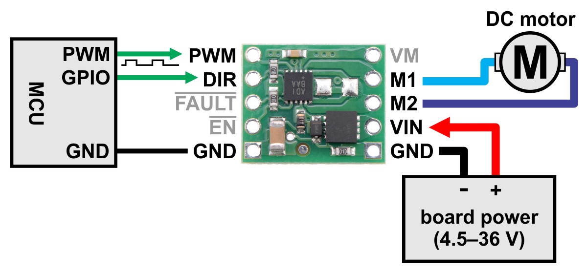
H bridge connections. Source: Pololu website
- Connect the 9-volts power supply to the pins VIN and GND, paying attention to NOT reverse polarity (see figure).
- The load will be connected to the pins M1 and M2.
- Connect the two GND pins and the EN pin, to a common ground.
- The MAX14870 resolves internally the configuration of the switches S1-S4 of previous section. You will need just two signals to control your load: a direction signal for the DIR pin (ON / 3.3V = M1 > M2; OFF / 0V = M1 < M2), and a PWM signal for the PWM pin (ON = voltage supplied, OFF = load is at ground).
Typically, the microcontroller sets the DIR pin low or high, depending on the direction of the desired voltage supplied to the load. The microcontroller also sends a PWM signal to the PWM pin with a given duty cycle. As a consequence, the voltage between M1/M2 pins will be an average value between 0V and 9V proportional to the PWM duty cycle. Overall, the MAX14870 Driver essentially operates as an amplifier.
Regulation of the brightness of a halogen bulb
Connect PWM and DIR pins of MAX14870 to the microcontroller pins PA_7/D11 and D5, respectively. Connect the two pins of the halogen bulb to pins M1 and M2.
The following code regulates the brightness of the halogen bulb. Edit the duty cycle to change the brightness.
#include "mbed.h"

PwmOut pwmbulb(PA_7);
DigitalOut DIR(D5);

int main() {

        DIR = 1;
        pwmbulb.period_us(1000);
        pwmbulb.write(0.1f); //NEVER go above 0.5f.
        printf("pwm set to %.2f %%\n", pwmbulb.read());

        wait(2);
        pwmbulb.write(0.0f);
}
The code is very similar to the LED one. In fact, we have just added an amplifier to drive more consistent loads. The last two lines of the code turn off the driver after two seconds, to avoid termal issues (the bulb drains a lot of current, which makes both bulb and driver becoming hot very fast).